Difference between revisions of "Manage dams for sediment flow"
(→Manage dams for sediment flow) |
(→General description) |
||
| (2 intermediate revisions by one other user not shown) | |||
| Line 1: | Line 1: | ||
=Manage dams for sediment flow= | =Manage dams for sediment flow= | ||
| − | Category | + | Category 02. Sediment flow quantity improvement |
==General description == | ==General description == | ||
| Line 10: | Line 10: | ||
When removing the sediments or even reducing the sediment volume in the reservoir of hydropower plants or other hydro facilities plant operators are faced with exorbitant costs of several million Euro range even for small reservoirs. Moreover, the various sediment removal procedures applied so far – flushing through the main valve, manual or sludge dredging – all have various additional negative secondary effects ranging from compromising the operation (up to plant shut down for several months), loss of huge quantities of water to negative morphological or ecological impacts. | When removing the sediments or even reducing the sediment volume in the reservoir of hydropower plants or other hydro facilities plant operators are faced with exorbitant costs of several million Euro range even for small reservoirs. Moreover, the various sediment removal procedures applied so far – flushing through the main valve, manual or sludge dredging – all have various additional negative secondary effects ranging from compromising the operation (up to plant shut down for several months), loss of huge quantities of water to negative morphological or ecological impacts. | ||
<br /> | <br /> | ||
| − | In contrast to those conventional approaches a controlled sediment transfer within the reservoir towards the reservoir outlet in a relatively small scale but permanent mode gives benefit to both reservoir maintenance and downstream hydromorphological situation. E. g. in the “ConSed”-process developed by University of Technology Aachen/Germany a permanently and automatically operated device allows for continuous and controlled transfer of sediment. Key element is an automatically working vessel with a suction dredging system installed that can be diesel or preferably electric driven | + | In contrast to those conventional approaches a controlled sediment transfer within the reservoir towards the reservoir outlet in a relatively small scale but permanent mode gives benefit to both reservoir maintenance and downstream hydromorphological situation. E. g. in the “ConSed”-process developed by University of Technology Aachen/Germany a permanently and automatically operated device allows for continuous and controlled transfer of sediment. Key element is an automatically working vessel with a suction dredging system installed that can be diesel or preferably electric driven. Sediments are loosened by a suction head, pumped towards the reservoir’s outlet and dumped in front of the outflow elements. The vessel gradually strikes the reservoir floor until the complete surplus sediment is removed. <br /> |
[[File:sediment transfer scheme small.png]] | [[File:sediment transfer scheme small.png]] | ||
| Line 36: | Line 36: | ||
==Case studies where this measure has been applied == | ==Case studies where this measure has been applied == | ||
| + | Continuous Sediment transfer is successfully being applied e.g. at Olsberg Reservoir of operator RWE since 2011. An automated vessel provides year round sediment transfer, except during ice coverage. Over time the vessel strikes the complete reservoir ground to transfer incoming sediment which deposited on the reservoirs floor. The sucked sediment is pumped to the aligned hydro power plant where the sediment is dropped in front of the turbine inlet and transferred through the turbine to the downstream river. The turbine ensures a good mixing with the outflow. Turbine components are not affected at the given sediment ratio.<br /> | ||
| + | |||
| + | A scaling instrument aboard the vessel allows for automatically adjusting a sediment transfer volume which suits to the actual plant/reservoir outflow and downstream compatibility. Transfer capacity at this application is up to 20 t/day, depending on the reservoirs outflow. The downstream river as well as the reservoir itself experienced a significant increase in ecological condition assessment within only weeks.<br /> | ||
| + | |||
| + | [[File:V 101 Agger.jpg]] | ||
| + | Automated Sediment Transfer Vessel (photo courtesy of DB Sediments). <br /><br /> | ||
| + | |||
<Forecasterlink type="getProjectsForMeasures" code="M15" /> | <Forecasterlink type="getProjectsForMeasures" code="M15" /> | ||
| + | |||
==Useful references == | ==Useful references == | ||
==Other relevant information == | ==Other relevant information == | ||
[[Category:Measures]][[Category:02. Sediment flow quantity improvement]] | [[Category:Measures]][[Category:02. Sediment flow quantity improvement]] | ||
Latest revision as of 12:16, 11 May 2022
Contents
- 1 Manage dams for sediment flow
- 1.1 General description
- 1.2 Applicability
- 1.3 Expected effect of measure on (including literature citations):
- 1.4 Temporal and spatial response
- 1.5 Pressures that can be addressed by this measure
- 1.6 Cost-efficiency
- 1.7 Case studies where this measure has been applied
- 1.8 Useful references
- 1.9 Other relevant information
Manage dams for sediment flow
Category 02. Sediment flow quantity improvement
General description
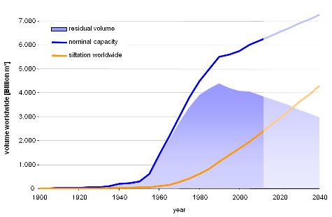
Almost every reservoir is affected by sedimentation. The World Commission on Dams estimated that each year almost 1 % of worldwide storage capacity is lost due to this effect. Even the actual new build of reservoirs does not level out over-all storage decrease. Dredging and disposing reservoir sediment is extremely expensive. On the other hand the sediment which is missing downstream of reservoirs leads to erosion damages, substrate deficits and ground water problems.

(data source: Jolanda Jenzer, Giovanni De Cesare: Möglichkeiten und Anwendung einer Datenbank bezüglich der Stauraumverlandung von alpinen Speichern, Wasser Energie Luft, 2006, Heft 3)
When removing the sediments or even reducing the sediment volume in the reservoir of hydropower plants or other hydro facilities plant operators are faced with exorbitant costs of several million Euro range even for small reservoirs. Moreover, the various sediment removal procedures applied so far – flushing through the main valve, manual or sludge dredging – all have various additional negative secondary effects ranging from compromising the operation (up to plant shut down for several months), loss of huge quantities of water to negative morphological or ecological impacts.
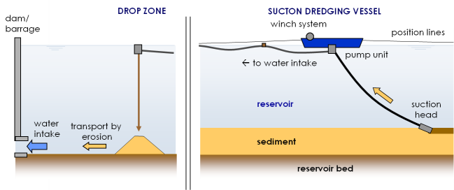
In contrast to those conventional approaches a controlled sediment transfer within the reservoir towards the reservoir outlet in a relatively small scale but permanent mode gives benefit to both reservoir maintenance and downstream hydromorphological situation. E. g. in the “ConSed”-process developed by University of Technology Aachen/Germany a permanently and automatically operated device allows for continuous and controlled transfer of sediment. Key element is an automatically working vessel with a suction dredging system installed that can be diesel or preferably electric driven. Sediments are loosened by a suction head, pumped towards the reservoir’s outlet and dumped in front of the outflow elements. The vessel gradually strikes the reservoir floor until the complete surplus sediment is removed.

ConSed-Process, Scheme: © DB Sediments
The newly dumped sediments are eroded by the hydraulic discharge and therefore carried out of the reservoir, passing turbines or outlet valves. Both types of outflow elements are able to handle water flow with some degree of sediment load. The sediment transfer rate can be adapted to the outflow rate and parameters to guarantee a compatible process speed. For an environmentally sound project implementation the time span should be set to months or years, depending on local conditions. A commercially competitive project performance is still assured by a high degree of automation.
Applicability
Sediment transfer at reservoirs can be applied on almost any reservoir size. Of course equipment needs to be adjusted for different dimensions. Available equipment is able to deal with water depths up to 20 m though no real constriction consists that would restrict operational range. In Switzerland tests with up to 160 m water depth have already been performed with successful results.
Sediment flow/removal often is not required for all accumulated sediment. From an operational standpoint it should be sufficient to establish a sediment transfer for the operating volume of a reservoir. The mass of continuous forwarded sediment will provide a benefit to downstream condition anyway, also for a later permanently installed sediment flow.
Expected effect of measure on (including literature citations):
- HYMO (general and specified per HYMO element)
- physico � chemical parameters
- Biota (general and specified per Biological quality elements)
Temporal and spatial response
Pressures that can be addressed by this measure
- Reservoir flushing
- Artificial barriers upstream from the site
- Artificial barriers downstream from the site
- Impoundment
- Sedimentation and sediment input
Cost-efficiency
Direct sediment transfer cost should be about the same than pure suction dredging. However, the major cost share on dredging work is not the suction, but dewatering and deposition of the "surplus" sediment which often makes up 80 % of overall cost. On a global view, also from pure cost perspective sediment flow/transfer is much more efficient than sediment removal, saving 80 % expenditures and landfill in this example.
As mentioned above the sediment leaves the reservoir via the usual outflow organs consisting of turbines, spillways, weirs etc. Wear on the discharge elements (e.g. turbine blades) remains within normal range unless sediment content is increased to a considerably high degree. Anyway, process benefit should easily outrange slightly higher rehab costs or useful turbine blade coating.
Case studies where this measure has been applied
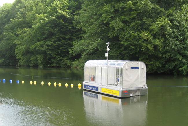
Continuous Sediment transfer is successfully being applied e.g. at Olsberg Reservoir of operator RWE since 2011. An automated vessel provides year round sediment transfer, except during ice coverage. Over time the vessel strikes the complete reservoir ground to transfer incoming sediment which deposited on the reservoirs floor. The sucked sediment is pumped to the aligned hydro power plant where the sediment is dropped in front of the turbine inlet and transferred through the turbine to the downstream river. The turbine ensures a good mixing with the outflow. Turbine components are not affected at the given sediment ratio.
A scaling instrument aboard the vessel allows for automatically adjusting a sediment transfer volume which suits to the actual plant/reservoir outflow and downstream compatibility. Transfer capacity at this application is up to 20 t/day, depending on the reservoirs outflow. The downstream river as well as the reservoir itself experienced a significant increase in ecological condition assessment within only weeks.
 Automated Sediment Transfer Vessel (photo courtesy of DB Sediments).